


Bosch LSU 4.2 / 4.9 wideband lambda sensor controller

Bosch wideband sensor (source: www.bosch.com)
The Bosch LSU wideband Lambda (oxygen) sensor
An oxygen sensor is used by all modern ECUs for internal combustion engines to determine the actual air/fuel ratio (AFR) by sensing the amount of oxygen present in the combustion gases.
The ideal value for a particolar combustion process can be found by using the Brettschneider equation (see this page for a detailed description), developed by J. Brettschneider in the seventies: this equation, given the concentration of each exhaust gas containing oxygen and the exact chemical composition of the fuel, returns the theoretical normalized Air-to-Fuel balance (identified with the Greek letter λ) for that particular combustion process, where normalized means that is normalized to the stoichiometric point, where every molecule of fuel reacts with every molecule of oxygen in a perfect combustion; for instance λ=1.1 would mean that the combustion is lean (10% eccess of oxygen) with respect to the stoichiometric point.
Bear in mind however that, in general, internal combustion engines make the maximum power with a slightly rich combustion, with an excess of fuel around 10-15% compared to the stoichiometric point.
From the lambda value the Air/Fuel ratio (A/F or AFR) can then be calculated by multiplying λ by a coefficient which depends on fuel type:
| Fuel type | Coefficient | AFR at λ=1 |
| Regular gasoline | 14.71 | 14.71 : 1 |
| E85 gasoline | 9.77 | 9.77 : 1 |
| E100 gasoline | 9.01 | 9.01 : 1 |
| LPG | 15.87 | 15.87 : 1 |
Knowing the AFR is then important when tuning an engine, especially if it has been turbocharged because a very lean (excess of oxygen) combustion can result in very high combustion temperature, quickly leading to engine failure.
Narrowband sensors use only one Nernst cell, whose voltage is proportional to the amount of oxygen: these sensors, while easy to use, have however a very nonlinear relationship between oxygen and output voltage and in particular have a very sharp 'knee' around λ=1, so are just used to detect a very rich (λ << 1) or very lean (λ >> 1) combustion (see image below).
These sensors have 4 pins: two for the heater, two for signal and it's return (ground).

Wideband or UEGO (Universal Exhaust Gas Oxygen) sensors use two nernst cells: one cell is used to measure the oxygen concentration by sensing the voltage Vs at it's terminals, the other one is used to pump oxygen ions in or out of the diffusion chamber by pumping current in/ out of the Ip terminal, in order to have a stoichiometric oxygen concentration in the chamber (Vs = 0.45V). This current has an almost linear relationship with the oxygen concentration for a wide range of λ and it's value and sign provide the necessary information to calculate λ.
These sensors have 6 pins: two for the heater, one for the common ground, one for Vs measurement, one for pumping the current Ip into the cell and one for measuring Ip as the voltage drop across a nominal 61.9 Ω resistor and they require a dedicated controller to work properly. The controller must:
- measure and regulate the sensor temperature to 750°C using the heater at terminals H+ H-
- measure the diffusion chamber voltage Vs to determine it's oxygen content
- regulate the diffusion chamber oxygen content to λ=1 (equivalent to 14.7 AFR for gasoline) by regulating the current Ip into/ out of the pump cell until Vs=450mV
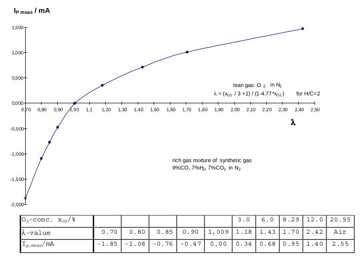
The actual lambda value is derived by sensing the current needed for the pump cell Ip and using a LookUp Table provided by the manufacturer (see image below).
The 30-300 Ω trimming resistor you see in the image is integral to the sensor connector and is laser-trimmed during production to compensate for the inevitable differences in the diffusion rate between sensors: this is done to avoid car manufacturers calibrating each sensor in the production line.

images taken from Bosch LSU 4.9 sensor datasheet
The Circuit
The schematic of the controller for Bosch LSU 4.2/ 4.9 wideband oxygen sensors is provided below. The INA2332 opamp is used to measure the Nernst voltage Vnernst, the pump current Ip and the heater impedance (used to calculate the sensor's temperature), which is obtained by measuring the voltage at the Vs pin resulting from a 250uA current pulse from pin PC6/PA7.
The microcontroller then controls Ip via an internal DAC connected to a Howland current pump circuit, which is used to regulate the diffusion chamber oxygen concentration.
The difference between the LSU 4.2 and 4.9 sensors is that the former takes the small amount of oxygen needed in the measurement chamber from the ambient air, while the 4.9 version needs a small current into the Vs pin to reach the same effect: R3 and R18 in the schematic provide this current and must be used only if using the LSU4.9 version.
Note that ICs part numbers are critical for accuracy since they were chosen using an error budget calculator (see Error budget RevB.pdf) in order to obtain an accuracy on the lambda measurement matched to the one of the sensor (+/- 0.007 λ for a new sensor, corresponding to +/-0.1 AFR for normal pump gasoline).
Both an external display (for three multiplexed 8-segment LED displays) output and a USART output are provided.

WBO2 controller schematic
The Firmware
The firmware is not available yet since it is still in 'alpha' stage...
References:
- Bosch LSU 4.2 and 4.9 Sensor datasheet
- US Patent US 8670920 B2: UEGO sensor air-fuel ratio determination system and method (Bowling, Grippo) - 2014
- US Patent US 6334352 B1: control device for a linear oxygen sensor (Poggio) - 2002
- US Patent US 8486255 B2: system, apparatus, and method for measuring an ion concentration of a measured fluid (K. Allmendinger) - 2013
Downloads
| File Name | Description | Download |
|---|---|---|
| WBO2_project.zip [NOT AVAILABLE YET] | Wideband controller project (schematics, PCB layout, etc.) |
|
| WBO2_FW.zip [NOT AVAILABLE YET] | firmware |
|
| Error_budget_RevB.pdf | Complete error budget for the controller |
|
| Lambda_Sensor_LSU_4.2_Datasheet.pdf | Bosch LSU 4.2 Datasheet |
|
| Lambda_Sensor_LSU_4.9_Datasheet.pdf | Bosch LSU 4.9 Datasheet |
|